Audio Processing Using Basic DSP Techniques
Prepared by: James Eastham, Member IEEE
In this tutorial we will use an audio signal as a practical example of common DSP techniques. We will apply the concepts of sampling, time-domain analysis, spectral analysis, and digital filtering. We will load an external sound file in wav format into Matlab for this analysis. Basic Matlab plots will be used to display our results. The Spectrogram will also be introduced.
Before we start, let’s review audio frequencies. Taken from Wikipedia: “An audio frequency is characterized as a periodic vibration whose frequency is audible to the average human. While the range of frequencies that any individual can hear is largely related to environmental factors, the generally accepted standard range of audible frequencies is 20 to 20,000 hertz. Frequencies below 20 Hz can usually be felt rather than heard, assuming the amplitude of the vibration is high enough. Frequencies above 20,000 Hz can sometimes be sensed by young people, but high frequencies are the first to be affected by hearing loss due to age and/or prolonged exposure to very loud noises.
We will use the Wikipedia definition as a guide to help us filter the audio signal.
To load the wav file (Pule Code Modulated file) we use the wavread function in Matlab. We need to know the sample frequency that was used to produce the file to play it at the correct speed. The following code will open the file and play it using the soundsc function.
clear all; %clears all variables
close all; %closes all plots
fs=8000; %sample frequency
Ts=1/fs; %sample period
n=0:3.5*fs-1; %sample index (fs=samples per second), 3.5 seconds
tn=n*Ts;
y = wavread('fp3.wav'); %open the message
y=y(1:28000); % This simply trims the file to the desired length
Plotting the Audio File in the Time domain:
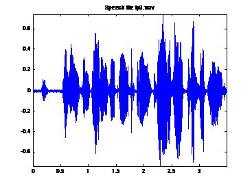
The following code will plot the audio file in the time domain.
figure('Color',[1 1 1]);
plot(tn,y);
axis('tight');
title('Speech file fp3.wav');

Plotting the Audio File in the Frequency Domain:
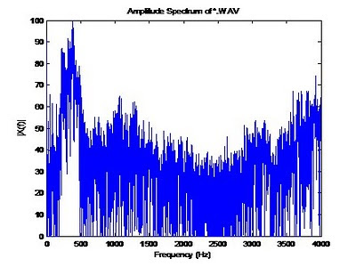
The following code will plot the audio file in the frequency domain. This section uses the ComputeSpectrum function we created in a previous blog post. Notice the spectral content, most of the content is below 500Hz. This is good, this is what we expect from an audio signal.

%******** Amplitude Spectrum of *.wav file *************
figure('Color',[1 1 1]);
[X,f] = ComputeSpectrum(y,fs,2^14);
plot(f,20*log(X));
title('Amplitude Spectrum of *.WAV');
xlabel('Frequency (Hz)');
ylabel('|X(f)|');
axis([0 4000 0 100]);
Filtering the Audio File:
Next we will use digital filtering to filter out undesired signals from our audio file. Matlab provides many different filters, in this example we will use the Butterworth filter. To read more about the Butterworth filter see: http://en.wikipedia.org/wiki/Butterworth_filter
The following code implements a tenth order (ten pole) low pass Butterworth filter with a cutoff frequency of 3400Hz. Cutoff frequencies are specified between 0.0 and 1.0 where 1 corresponds to half the sampling frequency: fs / 2 (4000 in our example). For example, for a cutoff frequency of 3400Hz, we specify this as 3400/(fs/2).
fNorm = 3400/(fs/2);
[b,a]=butter(10,fNorm,'low');
filterLow_y=filtfilt(b,a,y);
freqz(b,a,128,fs);
figure('Color',[1 1 1]);
plot(tn,filterLow_y);
axis('tight');
title('Speech file fp3.wav Low Pass Filtered at 200Hz');
soundsc(filterLow_y);
%******** Amplitude Spectrum of filtered *.wav file *************
figure('Color',[1 1 1]);
[X,f] = ComputeSpectrum(filterLow_y,fs,2^14);
plot(f,20*log(X));
title('Amplitude Spectrum of *.WAV');
xlabel('Frequency (Hz)');
ylabel('|X(f)|');
axis([0 4000 0 100]);
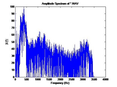
The figure below shows the frequency spectrum of the filtered signal; notice how all frequencies above 3400Hz are basically gone now.

Matlab provides the calculated coefficients if needed for later use or reporting. These are contains in the variables [a,b].
Filtering the Audio File (continued):
Matlab includes function the following Butterworth filters:
* 'low' : Low-pass filters, which remove frequencies greater than some specified value.
* 'high' : High-pass filters, which remove frequencies lower than some specified value.
* 'stop' : Stop-band filters, which remove frequencies in a given range of values.
To implement a ‘high’ pass filter, simply specify the cut off frequency as we did above, and use the ‘high’ keyword in the function call.
To implement the ‘stop’ band, a range must be defined. The following code will define this band. This code basically ‘chops’ out all frequencies from 750Hz to 950Hz.
% bandstop example
fNorm = [750/(fs/2), 950/(fs/2)];
[b, a] = butter(10, fNorm, 'stop');
The Spectrogram:
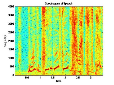
The spectrogram plot allows use to not only see which frequencies are present in our signal, but also when. Basic spectral analysis using the FFT does not allow us to see what spectral content is present at a given time. The spectrogram is a useful tool in spectral analysis. To display the spectrogram, the following code is provided. The 512 below is the number of samples that are used for the DFT, this becomes a grouping factor per column. Think of this as the granularity of the analysis, 512 is typically adequate for analysis. The spectrogram presents interpolated colors of magnitude vs. time. In the plot below, red for example means there is more frequency content at that frequency than say the light blue at a given time. Our audio file contains noise and voice harmonics therefore many frequencies are seen at any given time, however the magnitude of the voice range below 500Hz is see as the darkest (darkest red / black).
figure('Color',[1 1 1]);
specgram(y,512,fs);

3 comments:
very nice may i get extra material from u
thank you very much. I hope that these sharing would continue
Post a Comment